To develop a better understanding of the logic behind the Wheels Online Road Load Calculator and the use of its results, this discussion explains tractive demand and how it is computed. For an application, see the Example Code which implements this methodology.
Tractive Demand
Wheels computes the power and energy that a powertrain must successfully deliver to the wheels of a vehicle in order to make it achieve the velocities contained in a second-by-second driving cycle. This is known as the tractive energy and power demand, or tractive demand for short. It is independent of the powertrain configuration, which may or may not be supplied to the program. Given the vehicle's mass, drag coefficient, frontal area, rolling resistance coefficient, a few other parameters, and a driving cycle, a second-by-second history of tractive energy and power demands is computed. The computation is based on a simple equation-of-motion model of driving.
Wheels computes tractive demand in the following manner. Power is defined as energy per unit time. Energy is defined as force multiplied by distance. Therefore, to know either the power or energy demanded by a vehicle, one must first determine the forces that oppose the motion of the vehicle from the perspective of the wheels. Then, the energy expended during a given time increment can be found by multiplying the average force that acts during the increment by the distance traveled during the increment. Finally, the average power demanded during the increment can be found by dividing the energy demanded during the increment by the time increment. If the time increment is unity (one second), the power calculation is unnecessary because power demand is numerically equivalent to energy demand. For instance, power demand expressed in Watts would equal the energy demand in Joules if the time increment is one second, since a Watt is defined as one Joule per second.
The force opposing a vehicle in motion consists of several components:
where
Ftot = total (resultant) force
FRR = force due to tire rolling resistance
FAD = force due to aerodynamic drag
FI = force necessary to overcome inertia (acceleration, deceleration, and traversing a grade)
Tire rolling resistance FRR
The force due to rolling resistance is a function of many factors such as tire design, inflation pressure, vehicle weight, and speed. The primary mechanism behind rolling resistance is the deformation of the tire as it rolls under the weight it supports, and the friction of contact with the road surface. This deformation and friction absorbs energy which becomes dissipated to the environment as heat. This is why tires become warm while driving.
Given a tire design and a standard inflation pressure, a rolling resistance coefficient CRR can be found. CRR is a dimensionless quantity that describes resistance to forward motion per unit vehicle weight. Normally the resistance and weight terms are expressed in the same unit, such as lbf, so that the quotient is dimensionless. Properly, CRR varies somewhat with velocity, so some models provide additional CRR terms that are velocity-dependent. However, it is common for these terms to be neglected because the velocity-dependent effect is relatively small at reasonable city and highway driving speeds.
Wheels uses only the velocity-independent CRR term. Rolling resistance force then becomes a function of CRR and vehicle weight. The equation for FRR is:
where m = vehicle mass (kg)
g = 9.8 m/s2 (gravitational constant)
CRR = lbf/lbf or N/N (dimensionless)
Aerodynamic Drag FAD
Aerodynamic drag is created by the displacement of air as the vehicle moves, the friction of the moving air with the vehicle surface, and turbulence in the wake of the vehicle. The force due to aerodynamic drag depends mainly on the shape of the vehicle, the density of the surrounding air, and the velocity of the vehicle. It can also depend on the velocity of wind relative to the vehicle if the modeler chooses to account for it.
Vehicle shape is described by use of a dimensionless drag coefficient (CD) and the projected frontal area of the vehicle (AF). CD is usually determined experimentally, while AF is a simple area measurement that is often made photographically. Some analysts account for additional effects such as ground effect or yaw angle, but these enhancements are minor and are omitted here for simplicity.
The equation for force due to aerodynamic drag in still air is:
where
rho = density of air (kg/m3)
CD = drag coefficient (dimensionless)
AF = projected frontal area (m2)
V = vehicle velocity (m/s)
V is the average velocity during a time increment of the driving cycle. It is defined as
where
Vi = velocity at time increment i
Vi-1 = velocity at previous time increment i-1.
Thus the equation for aerodynamic drag force becomes
To account for wind, the modeler would need to know the component of wind velocity in the direction opposing vehicle travel and add that velocity to the average vehicle velocity in Equation (5). Currently, Wheels does not allow the user to specify wind velocity.
Inertia Force FI
The force due to inertia stems from changes in velocity (acceleration and deceleration). It is the product of the mass being accelerated (vehicle mass) and the rate of forward acceleration, as suggested by Newton's law F = ma. Unlike FAD and FRR, FI can be positive or negative. FI is positive (in opposition to vehicle movement) when accelerating, and negative (contributing to vehicle movement) when decelerating. There is also a rotational inertia force associated with the rotation of drivetrain components and a gravitational inertia force associated with hill climbing. These are accounted for separately below.
Forward acceleration is defined as the change in velocity v per unit time t. Expressed as a derivative it is dv/dt. The basic equation for FI is:
where
m = vehicle mass (kg)
dv/dt = acceleration (or deceleration) rate
During a given time increment, dv/dt can be calculated as the change in velocity during the time increment divided by the time increment. This yields an average acceleration rate, a, expressed as
where Vi = velocity at time increment i
Vi-1 = velocity at previous time increment i-1
tinc = duration of time increment
If the standard time increment is one second (unity), it can be omitted from the expression.
Thus the equation for the inertial force of forward acceleration becomes
Equation (8) does not account for the inertia of rotating or reciprocating elements in the drivetrain such as wheels, driveshaft, pistons, and the like. Changes in the speed of these components will absorb or return momentum, just as does the forward acceleration of the vehicle mass.
An accurate accounting of rotational inertia would require the modeler to know the masses and moments of inertia of all of the rotating components, and to provide enough information about their behavior to allow the software to keep track of their speeds. Rather than placing this burden on the modeler, Wheels and many other models approximate rotational inertia by using a rotational inertia compensation factor (r) to increase the vehicle's apparent mass in the FI term by 3% to 4%. This creates an increase in computed forward inertia that is similar in magnitude to the rotational inertia of a typical conventional powertrain. This technique may not be as valid for hybrid powertrains that have more, fewer, or more or less massive rotating elements than conventional vehicles, or where their rotational speeds are not directly related to forward velocity. Fortunately the effect is relatively small: the increase in inertia brought about by r=1.04 (4%) would result in the same increase in power demand that would result from a 4% increase in vehicle weight. The effect on energy consumption is minimal because much of the energy absorbed when a component spins up returns as it spins down.
The rotational inertia compensation factor (r) is a number greater than 1, such as 1.03 which would represent an imaginary 3% increase in vehicle mass. The equation for inertia force due to forward acceleration and rotational inertia becomes
As a vehicle ascends a grade, the force of gravity imposes an additional energy demand equal to the potential energy being invested in the vehicle due to the change in elevation. As the vehicle descends, the energy is returned. The grade of a hill is typically described in terms of its inclination from the horizontal in degrees or radians, referred to as theta (q).
The force of gravity is determined by the mass of the vehicle and the gravitational constant. The downward force on an object exerted by gravity is simply its weight:
We need to find Fq, the component of Fg that acts in the direction of q. A free body diagram will show that Fq = Fg sin q. The gravity force equation becomes
As expected, a level grade (q = 0 degrees) translates to zero Fq since sin 0 = 0. Grade is usually taken to be zero when estimating fuel economy. Grade may be set to other values when the intent is to measure power demand up a grade.
The final equation for inertia force due to forward acceleration, rotational inertia, and grade becomes
Tractive power and energy equation
Now that the forces acting on the vehicle are known, we have all of the information necessary to compute tractive power and energy demands. Here we choose to compute power demand, knowing that it is numerically equivalent to energy demand as long as the time increment is one second.
Power is energy per unit time. Since energy is force multiplied by distance, and velocity is distance per unit time, it can be shown that power is force multiplied by velocity. Thus the tractive force equation
Ftot = FRR + FAD + FI (1)
can be multiplied by velocity V to yield tractive power:
Substituting the definitions of the component forces (Equations 2, 5, and 12) and the mean velocity equation (Equation 4), the tractive power demand equation becomes:
where Ptractive = average tractive power demand during time increment (Watts)
m = vehicle mass (kg)
g = gravitational constant (9.81 m/s2).
CRR = tire rolling resistance coefficient
rho = density of air (kg/m3)
CD = drag coefficient
AF = projected frontal area (m2)
Vi = velocity at current time increment (m/s)
Vi-1 = velocity at previous time increment (m/s)
r = rotational inertia compensation factor
q = road gradient (degrees from horizontal)
The power demanded at the wheels by any vehicle, conventional or hybrid, is accurately defined by the above equation. All other factors that influence fuel economy, including accessories, are powertrain-dependent.
Computation Procedure
Wheels first calculates the mean acceleration rate (a) and mean velocity (V) during a time increment by Equations (4) and (7). Then the total force Ftot (Equation 1) and the inertia force FI (Equation 12) are computed in order to distinguish between various driving modes such as positive acceleration, deceleration, and braking. Finally, it evaluates the tractive power Ptractive (Equation 14) in one of several ways depending on the driving mode.
Identification of Driving Modes
Figures 1-5 show the various driving modes that can exist on a level grade as determined by the sign and magnitude of component forces. The total force Ftot acting on the vehicle is always the sum of the component forces FAD, FRR, and FI.
Since FI can be positive or negative, sometimes it contributes toward defraying FAD and FRR so that the powertrain need only provide enough new energy to cover what remains. This makes it helpful to distinguish between "gross" and "net" FAD and FRR in Figures 1-5. The gross quantities are the actual forces that occur at the wheels; the net quantities are the portions remaining for the powertrain to provide after any negative FI (if any) is credited.
When FI is positive, velocity is increasing so the vehicle is accelerating. When FI is zero, the vehicle is cruising at constant speed. When FI is negative, the vehicle is decelerating. Deceleration consists of several modes distinguished by the magnitude of FI: powered deceleration, free coastdown, and braking.
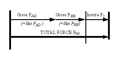
Figure 1. Acceleration |
Positive Acceleration
When the total force is positive and the inertia force is also positive, the vehicle is accelerating. This condition is illustrated in Figure 1. In this case power is being dissipated by FAD and FRR and "invested" in FI. The energy and power demand is computed in a straightforward manner using the tractive power equation (14). |
When the inertia force is negative (or zero) but not large enough in magnitude to render the total force negative as well, the vehicle is in one of three conditions: constant-speed cruise, powered deceleration, or free coastdown as depicted in Figures 2-4 respectively. Cruise and free coastdown are special cases that are easy to evaluate by Equation (14).
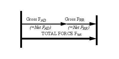
Figure 2. Constant speed cruising |
Cruising Cruise occurs when inertia force is zero due to constant velocity; Ptractive is computed as for acceleration except the inertia term evaluates to zero. |
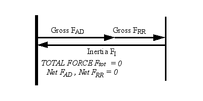
Figure 3. Free Coastdown |
Coastdown Free coastdown occurs when the demands of tire rolling resistance FRR and aerodynamic drag FAD just happen to be offset by the returning inertia force FI, forcing Ftot and Ptractive to zero. |
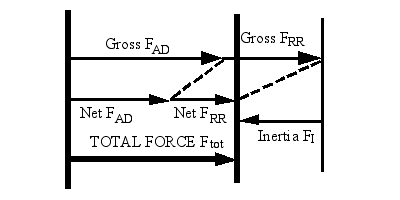
Figure 4. Powered deceleration |
Powered deceleration Powered deceleration is a more common condition. It occurs when FI is negative but not enough to completely offset FRR and FAD. Physically, the vehicle is decelerating at a gentle rate, not quite as rapidly as a free coastdown. As a result energy is still being demanded at the wheels by FAD and FRR in order to keep the velocity a bit higher than that of a coastdown. But since a portion of FAD and FRR is already being met by returning inertia force that was previously accounted for, one can only count the new or "net" FAD and FRR that must be made up by the powertrain. The net force is the difference between the gross FAD + FRR and the returning FI. For accounting purposes, the net force is appropriated between FAD and FRR in proportion to their respective shares of the total gross demand as depicted in Figure 3.
|
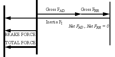
Figure 5. Braking
|
Braking
When the inertia force is negative and is large enough in magnitude to render the total force negative as well, the vehicle is braking. Physically, this means that deceleration is so rapid that FAD and FRR are not sufficient to cause it, and hence the excess inertia energy must be consumed by other means. In practice, the excess inertia energy can either be dissipated by applying friction brakes, or absorbed by a regenerative braking system. FAD and FRR are being met entirely by the returning inertia force, so by definition Ptractive is zero. The excess inertia force is equal to the total inertia force minus that consumed by FRR and FAD. It is also equal to the total force Ftot, which is negative.
|
Idling is a special case where total force, inertia force, and velocity are all zero. By definition, tractive energy is zero under these conditions.